Question 2 Draw The Sfd And Bmd For The Following Chegg Com from media.cheggcdn.com Sheer force diagram (sfd) and bending moment diagram (bmd) are the most important first step toward design calculations of structural or machine elements. Shear force and bending moment. The shear force diagram (sfd) and bending moment diagram (bmd) of a beam shows the variation of shear force and bending moment along the length of the beam. What is sfd and bmd, types of supports and beams. In sfd and bmd diagrams shear force or bending moment represents the ordinates, and the length of the beam represents the abscissa. Beamguru.com is a online calculator that generates bending moment diagrams (bmd) and shear force diagrams (sfd), axial force diagrams (afd) for any statically determinate (most simply supported and cantilever beams) and statically indeterminate beams, frames and trusses.the calculator is fully customisable to suit most beams, frames and trusses; Draw sfd and bmd for the single side overhanging beam. Sfd & bmd shear force & bending moment diagram 1.
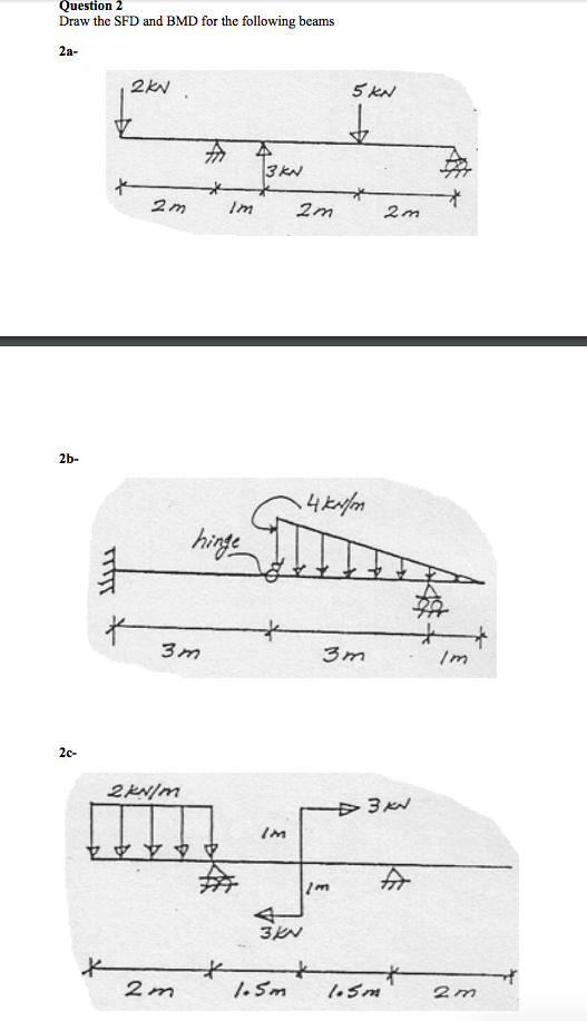
Draw sfd and bmd for the single side overhanging beam.
Draw sfd and bmd for the single side overhanging beam. Click to expand document information. Fbd = free body diagram; Sfd and bmd can be plotted without determining support reactions since it is a cantilever beam. The shear force diagram (sfd) and bending moment diagram (bmd) of a beam shows the variation of shear force and bending moment along the length of the beam. 3 integration method for sfd and bmd example 1.2 derive equations for the shear force and bending moment of the beams loaded as shown below. 100% (1) 100% found this document useful (1 vote) 577 views 99 pages. Diagrammatic convention for supports roller supports hinge support fixed support link support fig. If the right portion of the section is chosen, then the force acting. Shear force bending moment 4. A bending moment diagram is the graphical representation of the variation of he bending moment along the length of the beam and is abbreviated as b.m.d. If p = 20 kn and l = 6 m, draw the sfd and bmd for the beam. This video is highly rated by mechanical engineering students and has been viewed 607 times.
Click to expand document information. 3 integration method for sfd and bmd example 1.2 derive equations for the shear force and bending moment of the beams loaded as shown below. To draw a shear force diagram, first find value of shear force between varying loads. Also draw the corresponding sfd and bmd. Works with ssb, cantilevers, overhangs, and beams with internal hinges.
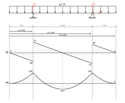
Beamguru Com Beam Calculator And Frame Truss Beam Calculator Online Draws Bending Moment Shear Force Axial Force from beamguru.com The net force to the left of the section perpendicular to the beam. Shear force and bending moment beam: As with all calculations/formulas care must be taken to keep consistent units throughout with examples of units which should be adopted listed below: Jahangirabad instiute of technology barabanki department of mechanical engineering elements of mechanical engineering ravi vishwakarma 31/12/16 ravi vishwakarma 1 2. For different loadings of the strength of materials are explained in this video. 1)the shear force at any section in a beam is ___________. Sfd and bmds are properly annotated, showing the maximum, minimum and all nodal values of shear force and bending moment on the beam. Example on simply supported beam 7.
Shear force & bending moment diagram of simply supported beam by jalal afsar shear force and bending moment diagram of simply supported beam can be drawn by first calculating value of shear force and bending moment.
Shear force bending moment 4. This video is highly rated by mechanical engineering students and has been viewed 607 times. Shear force & bending moment diagram of simply supported beam by jalal afsar shear force and bending moment diagram of simply supported beam can be drawn by first calculating value of shear force and bending moment. What is sfd and bmd, types of supports and beams. The net force to the right of the section perpendicular to the beam. The above beam design and deflection equations may be used with both imperial and metric units. Example on simply supported beam 7. All 3)for uniformly varying load load(uvl) the degree of curve is 2nd (parabola) in sfd and 3rd(cubic parabola) in bending moment diagram(bmd). Which is a feature unavailable on most other. The shear force diagram (sfd) and bending moment diagram (bmd) of a beam shows the variation of shear force and bending moment along the length of the beam. The load which is perpendicular or it has non zero component perpendicular to longitudinal axis of beam. Shear force value increases gradually as we move towards fixed end. The net force to the left of the section perpendicular to the beam.
The net force to the left of the section perpendicular to the beam. Shear force and bending moment. Draw the shear force v and bending moment m diagrams for beams shown below study. However, values of sf and bm are substantiated at the support if support reactions are identified. Sfd, bmd for cantilever beams, simply supported beams and overhanging beams considering point loads, udl, uvl, coupledocuments.
Sfd And Bmd Of Beam Shear And Civil Engineering Store Facebook from lookaside.fbsbx.com It is a structural member which is subjected to transverse load. Shear force and bending moment. 1)the shear force at any section in a beam is ___________. If the right portion of the section is chosen, then the force acting. Support conditions axial force, shear force and bending moment three forces are required to maintain internal equilibrium at every section of a beam. For different loadings of the strength of materials are explained in this video. Also draw the corresponding sfd and bmd. Calculate the reactions at the supports of a beam.
Works with point loads, pure couples, udls, and uvls, and combination of these loads at the same time.
About press copyright contact us creators advertise developers terms privacy policy & safety how youtube works test new features press copyright contact us creators bmd sfd. The shear force diagram (sfd) and bending moment diagram (bmd) of a beam shows the variation of shear force and bending moment along the length of the beam.


0 Komentar